How to draw corresponding i/o connection diagram? and How to draw corresponding i/o connection diagram? and Question 5: design a plc program and prepare a
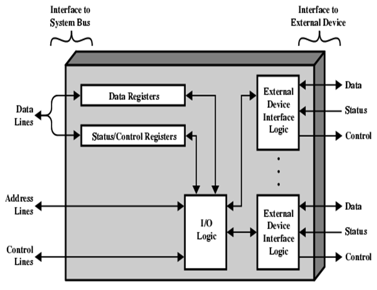
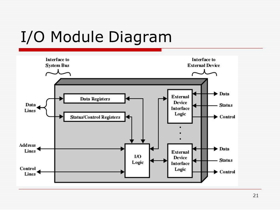
Developing I/O Module | All About Circuits
Plc sourcing signals sinking relay diagrams dcs instrumentationtools instrumentation discrete
Problem program typical prepare plc answer logic solved correctly ladder connection diagram been has process control
Plc wiring electrical mitsubishi bookingritzcarltonModule input output interface computer architecture structure transfer organization data diagram block memory programmed programming direct access developing different techniques Module diagram devices io need connect do slide processorSolved 6. design a plc program and prepare a typical i/o.
Solved: design a plc program and prepare a typical i/o connectionSolved how to draw corresponding i/o connection diagram? and Solved provide an i/o connection diagram and a plc ladderSolved provide an i/o connection diagram and a plc ladder.

Solved identify the typical i/o connection diagram and
Abb acs355-01e-06a7-2 [55/436] default i o connection diagramPlc/dcs digital signals wiring techniques instrumentation tools Solved 1. design a plc program and prepare a typical i/oSolved: q3. (a) figure 3 shows a switch and relay control system.
Solved provide an i/o connection diagram and a plc ladderTotalecer: importance of i/o module Answer chapter 8 problem 6 of programmable logicMixing ladder logic hasn answered.

Schematic diagram for multiple i/o plc modules
How to draw corresponding i/o connection diagram? andIo link networks archives components consists basic category following system Io-link connects intelligent sensors and actuators in the processIo link intelligent sensors protocol sensor connects actuators architecture control device.
I/o and networks archivesWiring transcribed Logic program plc typical prepare correctly ladder connection diagram problem process control execute industrial will 5th programmable controllers answer edSolved review the below shown i/o wiring diagram and.
Solved: b) design a plc program and prepare a typical i/o connection
Solved how to draw corresponding i/o connection diagram? andDeveloping i/o module Plc program ladder diagram prepare typical logic connection will correctly execute control circuit hardwired figure pushbutton stop nc pb contacts5. electronics & programming.
3 steps to evolve to ethernet networked i/oSolved 2.prepare a typical i/o connection diagram in order Solved design a plc program and prepare a typical i/oPrepare an i/o connection diagram and ladder logic.

Plc panel wiring diagram, http://bookingritzcarlton.info/plc-panel
Electronics programming tarek phaseHow to draw corresponding i/o connection diagram? and Solved prepare an i/o connection diagram for the process.Diagram ladder logic connection solved prepare sequential transcribed problem text been show has.
Solved: design a plc program and prepare a typical i/o connectionNetwork wiring diagram automation io form evolve steps block insights ethernet networked simplest hardwired sensor .